Home >> News >> Company News
Introduction to the Various Components of an Oil Drilling Rig |
作者:本站 发布时间:2025-03-10 浏览:64次 |
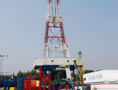
Lifting System of the Drilling Rig The lifting system is equipped on the drill tools to raise and lower the drilling tools, casing, and to control drilling pressure and feed the tools. The lifting system includes the winch, auxiliary brake, crown block, traveling block, hook, wire rope, and various tools such as the lifting rings, lifting slips, lifting tongs, and drill slips. When lifting, the winch drum winds the wire rope, and the crown block and traveling block form a pulley system. The hook rises, and through lifting rings, lifting slips, and other tools, the drilling tools are raised. When lowering, the tools or casing strings descend under their own weight, controlled by the winch’s brake system and auxiliary brake to manage the descent speed of the hook. During normal drilling, the brake system controls the feed speed of the drill tools, applying part of the tool's weight as drill pressure on the bit to break the rock formation. Rotary System The rotary system is a typical system in rotary table drilling rigs. Its function is to rotate the drill tools to break the rock formation. The rotary system includes the rotary table, swivel, and drill tools. Depending on the type of well being drilled, the composition of the drill tools may vary, generally including square drill rods, drill rods, drill collars, and drill bits. Additionally, there are stabilizers, shock absorbers, and coupling joints. The drill bit is the tool directly responsible for breaking the rock, with types such as scraper bits, roller cone bits, and diamond bits. The drill collar is heavy and thick, used to apply drill pressure to the bit. The drill rods link the surface equipment and bottom hole equipment, transmitting torque. Square drill rods typically have a square cross-section, and the rotary table rotates the entire drill string and bit via the square rod. The swivel is a typical component of a rotary drilling rig; it not only bears the weight of the drill tools but also enables rotary movement, while providing a passage for high-pressure drilling mud. Circulation System The circulation system is used to transport the rock cuttings generated by the drill bit to the surface for further drilling operations and to cool the drill bit, protect the wellbore, and prevent drilling accidents such as well collapse or loss. The circulation system includes the drilling pump, surface manifold, mud tank, and mud purification equipment. The surface manifold includes high-pressure manifold, standpipe, and rotary hose, while the mud purification equipment consists of shale shakers, desanders, desilters, and centrifuges. The drilling pump draws mud from the mud tank, and after being pressurized by the pump, the mud flows through the high-pressure manifold, standpipe, and rotary hose to the swivel, where it enters the hollow drill tools and reaches the bottom hole. The drilling fluid is ejected through the bit nozzles, carrying rock cuttings back to the surface through the annular space between the drill tools and the wellbore. The returned mud undergoes purification by various mud purification equipment to remove solid-phase content and is then reused. Power Equipment The lifting system, circulation system, and rotary system are the three main working units of the rig, providing power for drilling operations. To power these units, the rig must be equipped with power equipment. The power equipment of a drilling rig includes diesel engines, AC motors, and DC motors. Diesel engines are suitable for remote areas without an electric grid. AC motors rely on the industrial power grid or use a diesel engine to generate AC power. DC motors require a diesel engine to drive a DC generator to produce DC power. The more common setup involves using a diesel engine to drive an AC generator, converting AC power to DC power via a silicon-controlled rectifier. Transmission System The transmission system converts and distributes the power and motion provided by the power equipment to various working units, meeting their different power needs. The transmission system typically includes reduction gear mechanisms, speed-change devices, forward-reverse mechanisms, and coupling systems between multiple power units. Drilling rigs directly driven by diesel engines often use a unified driving form, with relatively complex transmission systems. Drilling rigs driven by AC or DC electric motors typically use separate or grouped drives for each unit, greatly simplifying the transmission system. Control System The control methods include mechanical control, pneumatic control, electric control, and hydraulic control. The commonly used control method on drilling rigs is centralized pneumatic control. The driller can control almost all aspects of the rig through the driller's control panel, including clutch disengagement, coupling of power units, starting and stopping of the winch, rotary table, and drilling pump, as well as controlling the high and low speeds of the winch. Derrick and Substructure The derrick and substructure support and install the drilling equipment and tools, providing the drilling operation space. The derrick is used to install the crown block, suspend the traveling block, hook, swivel, and drill tools, bearing the drilling work load and discharging the standpipe. The substructure is used to install power units, winches, rotary tables, and support the derrick. It helps the rotary table suspend the drill tools and provides the necessary height space between the rotary table and the surface to install blowout preventers and facilitate the mud circulation process. Auxiliary Equipment In addition to the main components, a drilling rig includes other auxiliary equipment, such as blowout preventers (BOP) to prevent blowouts, generator sets to provide lighting and auxiliary power for drilling, air compressors for supplying compressed air, and equipment for providing water and oil.
|